Macy's Thanksgiving Day Parade and Intellectual Property

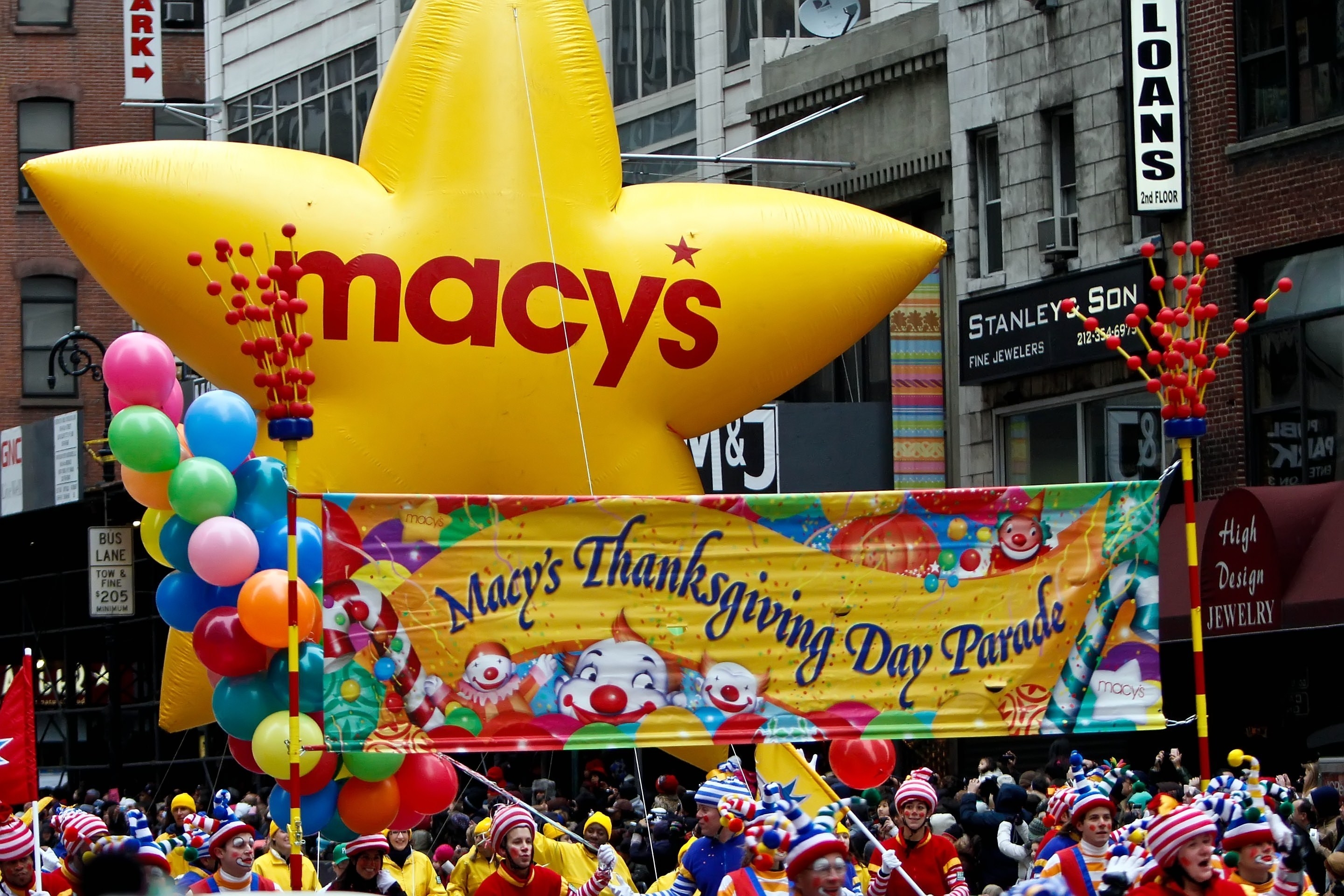
With Thanksgiving quickly approaching so are all the great traditions that come with the food filled holiday. One tradition that has been around since 1924, is the Macy’s Thanksgiving Day Parade in New York City. More than 3.5 million people watch the parade live and more than 50 million TV viewers watch nationwide. Over 10,000 people participate in the parade and the entire parade process takes more than 13 months of advance planning.
As with most things, intellectual property is a part of this parade as well. Macy’s has a federal trademark registration for the phrase MACY’S THANKSGIVING DAY PARADE that was issued on December 1, 1998 (U.S. Registration No. 2206890).
This year will be a special year for the parade as it marks the 90th anniversary. This will be the 90th parade since 1924. During the years of 1942-1944 the parade was temporarily suspended due to World War II. The rubber that would have been used for the balloons was donated to the American Military to help America’s cause.
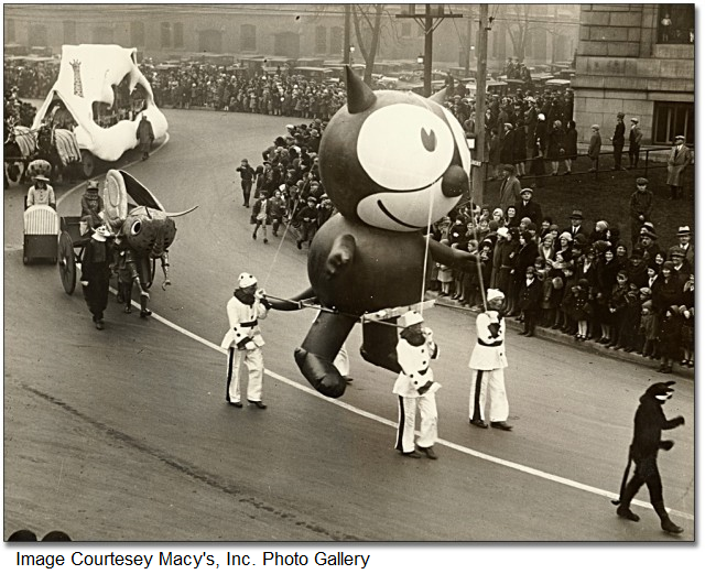 The first character balloon to be displayed at the Macy’s Thanksgiving Day Parade was that of Felix the Cat (Registration No. 1327241) in 1927, three years after the first parade. The balloons at that time were filled with oxygen not helium and were propped up by a team of puppeteers. In 1928, the balloons were filled with helium; the parade organizers did not have a plan for the balloons when the parade was over so in 1928 the parade organizers decided to just let Felix the Cat go. Unfortunately, Felix did not make it far as he popped shortly thereafter. The releasing of the balloons became a tradition for some years after. The balloons had a return address listed on them and if the balloon was returned, the returnee received a gift from Macy’s. Some other balloon characters to follow Felix were Bullwinkle, Underdog (Registration No. 2145933), and Mickey Mouse.
One cartoon character that has made more appearances in the parade over any other character is Snoopy (Registration No. 1300520). Snoopy first appeared in 1968, and has had more than seven balloons created for him. 2015, marked Snoopy’s 39th appearance in the parade but this year, it looks like Charlie Brown will be stealing the spotlight.
In 2008, Macy’s put its Thanksgiving parade in the hands of its fans by a flip book created by Flippies Inc. Today’s reengineered flip books have advanced  significantly since their introduction by Henry Van Hoevenbergh in 1882 (U.S. Patent No. 258,164). The patent pending technology of Flippies Inc.’s new flip book plays live-action video clips with crystal clear imaging with the flip of a thumb. "What's old isn't just new again, it's also improved" said Jeffrey Kay, President of Flippies. The books feature two favorite parade scenes, the pilgrimage of Tom Turkey and the finale of the parade, Santa’s arrival.
One company that has had a float for the past decade is Balsam Hill, a company that brings the special holiday feeling to many with their highly-realistic Christmas trees. Balsam Hill has a number of patents for their special trees such as INVERTIBLE CHRISTMAS TREE (U.S. Patent No. 8,993,077) and COLLAPSIBLE ARTIFICIAL TREE (U.S. Patent No. 9,040,130). This year, the company is planning on creating something unique and special for the 90th anniversary. They will dawn a 30 foot float with all things that embody Christmas.
The 90th Anniversary Macy’s Thanksgiving Day Parade airs nationwide on NBC-TV, on Thursday, Nov. 24, 2016 from 9 a.m. – noon in all time zones.
Patent of the Day: Recording Pen
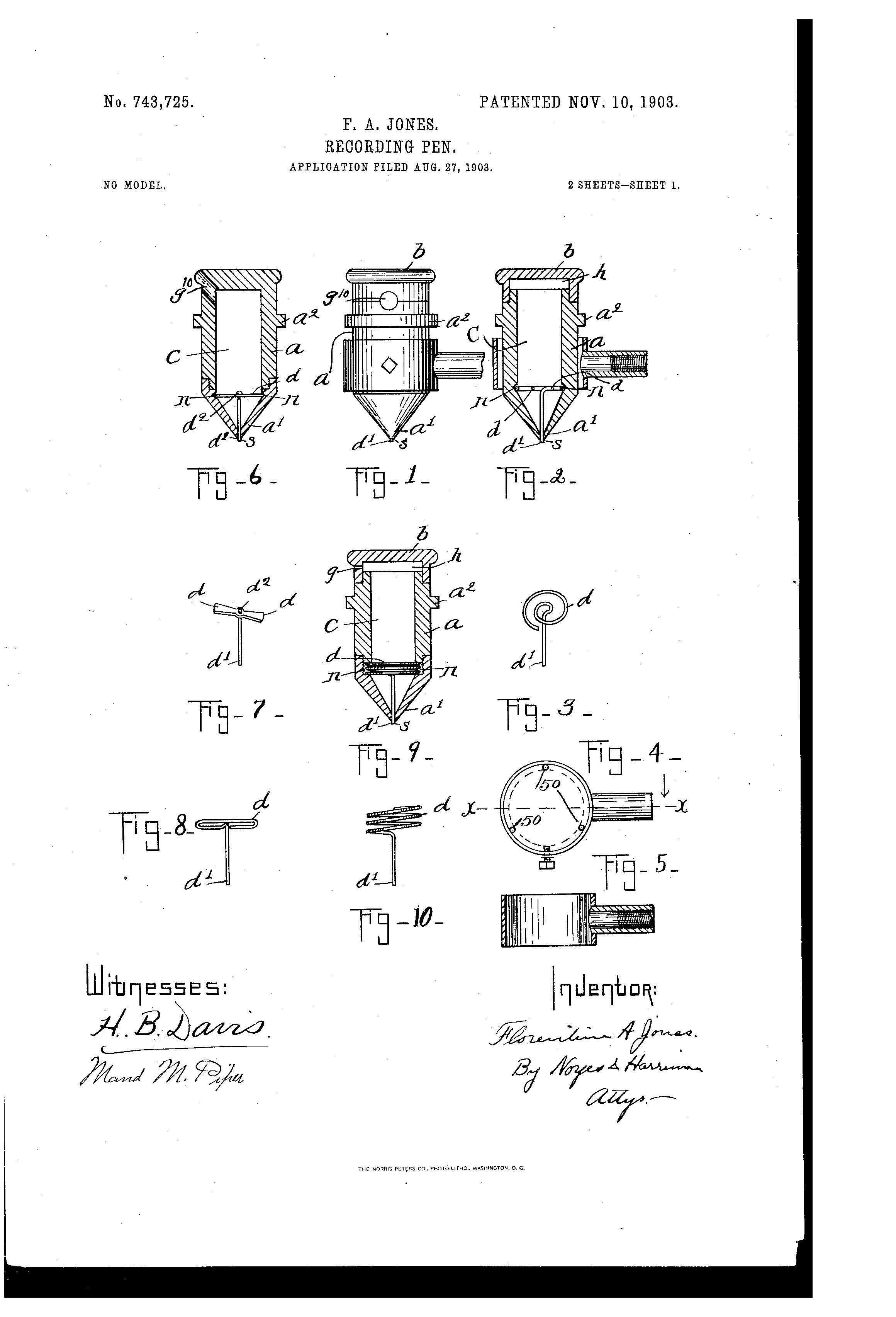
On this day in 1903 Florentine A. Jones was granted the patent for RECORDING PEN. U.S. Patent No. 743,725.
This invention relates to that class of pens or marking devices that are employed in connection with gages, thermometers or other instruments for recording pressures, temperatures, and their variations. Pens of this class are of necessity very small, and it is exceedingly difficult to conduct the ink from the interior of the pen to the chart or recording dial in a regular and even manner, so as to produce a clear line of a uniform width on the chart or dial, owing to the very small quantity of ink required. Under these conditions it will be readily understood that the ink recording wire or stylus should be protected as far as possible from all danger of derangement when in the hands of unskilled or careless persons.
The object of this invention is to produce means for holding the stylus in the fixed position properly adjusted to its work, said means being not only independent of the cap which is used to close the reservoir, but is concealed within the reservoir and there fore sufficiently inaccessible to be out of easy reach, so that the stylus cannot be readily deranged, and thereby prevented from working, and, furthermore, cannot be lost through carelessness or negligence. The stylus held in place by the means embodying this invention enables the reservoir of the pen to be filled with ink without removing the stylus and prevents its derangement or loss out of the pen.


Business Law for Entrepreneurs (Nov. 17)
On November 17, our Matt Poulsen and Jonathan Wegner from Baird Holm will serve as a panelists in a forum discussing business law for entrepreneurs, hosted by Start-Hear. Matt will focus on intellectual property as it relates to startups.
The discussion will be held at the Peter Kiewit Institute, Room 158 from 6-8PM
Patent of the Day: Aerial Vessel
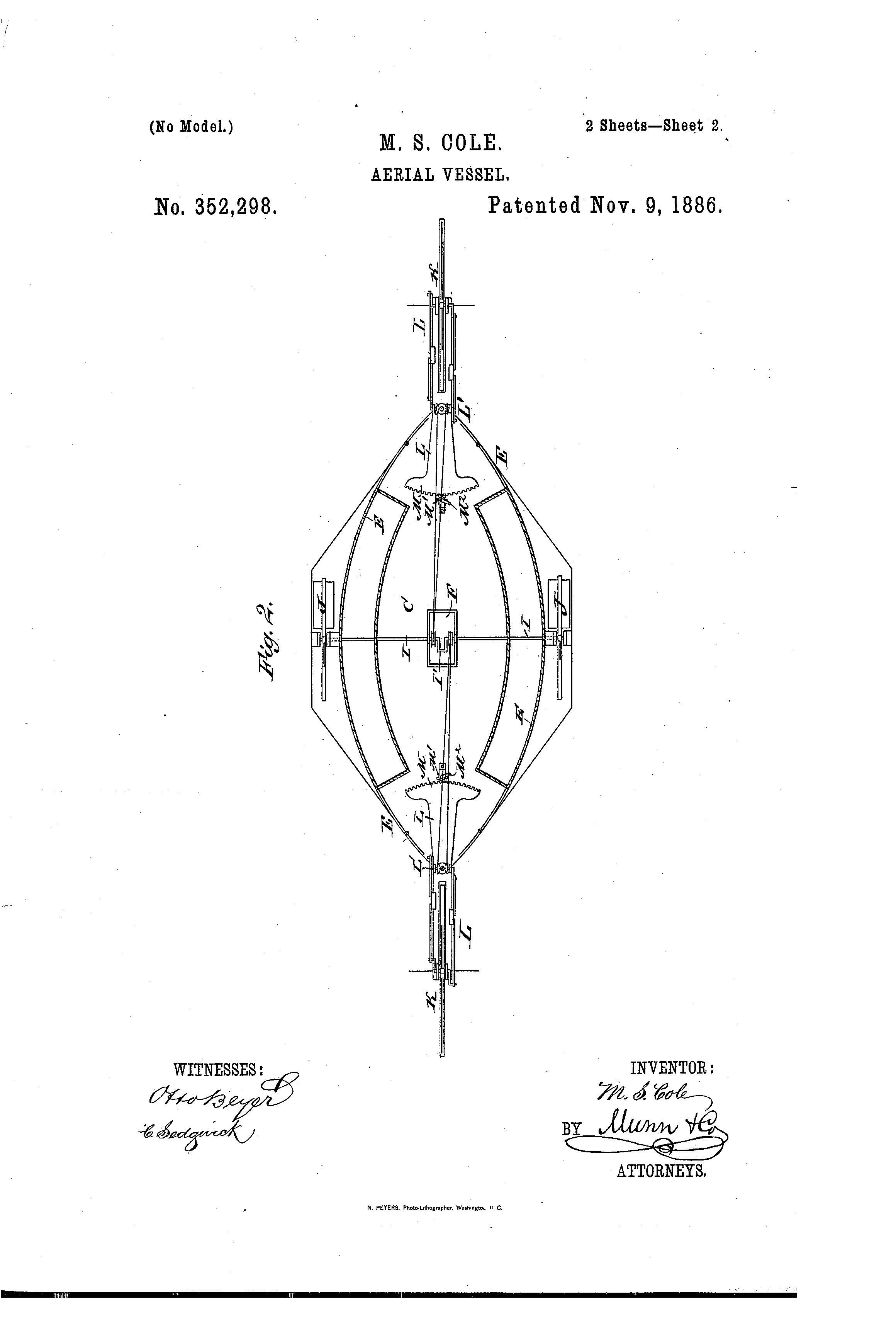
On this day in 1886 Moses S. Cole was granted the patent for AERIAL VESSEL. U.S. Patent No. 352,298.
The object of this invention is to provide a new and improved aerial vessel which can be raised, lowered, steered, and propelled in any direction at the will of the pilot.
The invention consists of an aerial vessel of novel construction, and of wheels for raising, lowering, steering, and propelling the same, operated from suitable machinery placed in side of the aerial vessel.
The invention also consists of various parts and details and combinations of the same.


Lost Car? Amazon Patents Mini-Drone that Can Help Locate It.

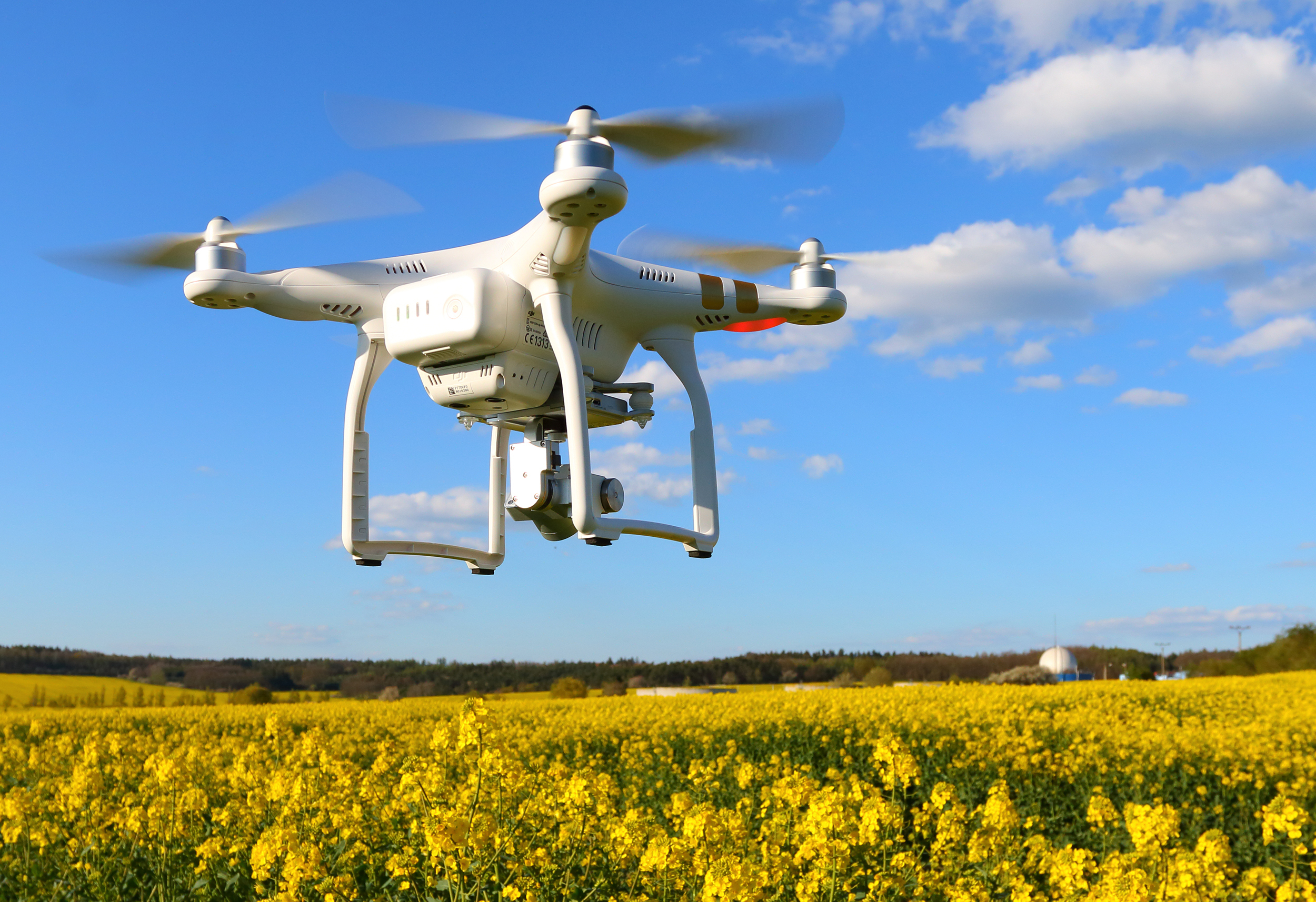
It happens to everyone. You park your car in a hurry and walk into the store only to realize when you leave the store you have no idea where your car is parked. The parking lot is crowded; there is no distinguishable marker by which you remember parking, and frustration sets in. Thanks to voice-activated technology being developed by Amazon and represented in U.S. Patent No. 9,471,059, entitled UNMANNED AERIAL VEHICLE ASSISTANT, one can simply say “locate car” and a tiny drone that is perched on your shoulder or somewhere close by will take off and locate your car.
This small drone, depicted as small enough to perch on a police officer’s radio, uses a technology that is described as an assistant that can act as the “eyes and/or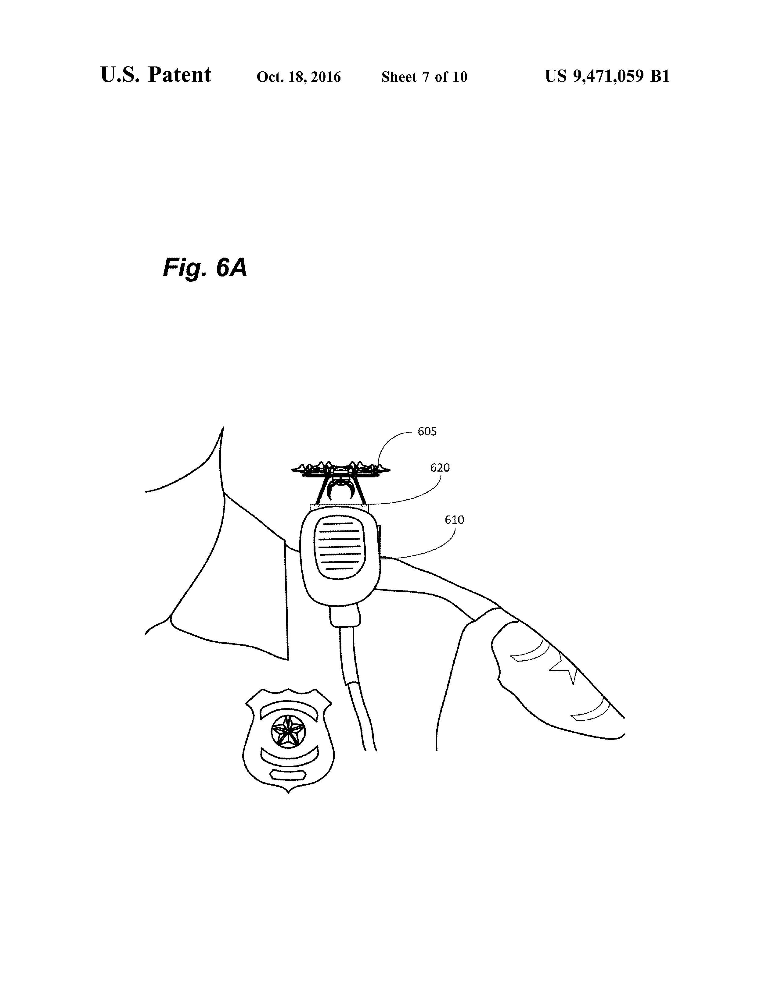 ears, among other things, for the user to extend the user’s perception.” The drone can accept many commands in different forms such as voice commands through a microphone, signals from an app, computer or internet application.
The patent filing details the drone to be helpful in situations “in which a user may wish to review the situation from afar. This may be because the user needs a different vantage point (e.g., to see over a crowd), because the situation is dangerous (e.g., a foxhole or an underground tunnel during a military maneuver), or because the user simply can’t find their car in a crowded parking lot.”
The patent filing further details situations in which the drone would be helpful. Parents, for instance, could use the drone to locate their child if he or she should go missing. The user would simply say “find Timmy” and the drone would be able to scan large crowds or areas for the child who would have a RFID tag sewn into their clothes or a bar code printed on their clothes.
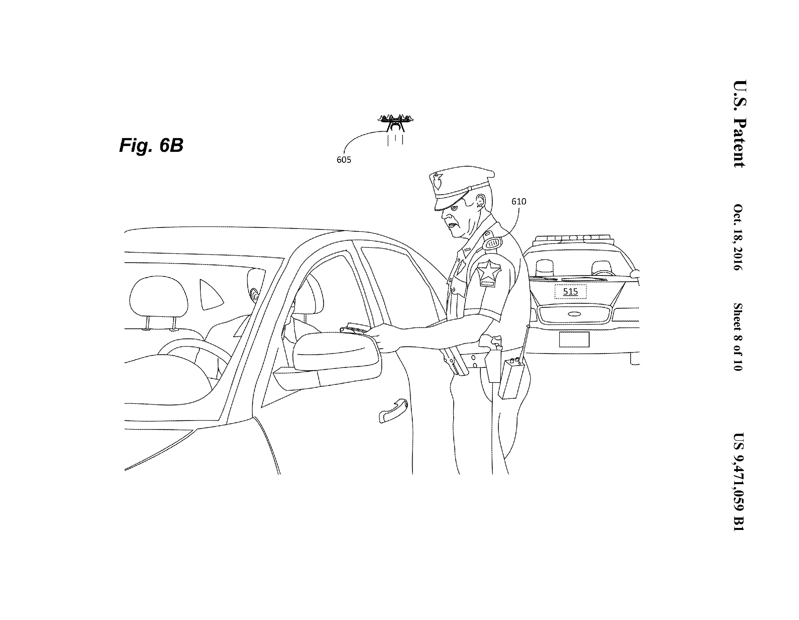 First responders would also greatly benefit from the use of the drone. Police could use the drone as an aerial dashcam providing a different point of view/angle for them. The drone could be used when officers pull someone over; it could fly around the car taking pictures of the vehicle and the vehicle’s occupants. It could also be used in a high-speed chase to take a picture of the driver of the car while reducing the risk of an officer driving at high speeds. Firefighters could benefit as the drone could identify people trapped in a burning building or to keep an eye out to make sure flare-ups after a fire are contained.
Although Amazon has not confirmed if they will manufacture this particular technology, it will be interesting to see how this technology develops.
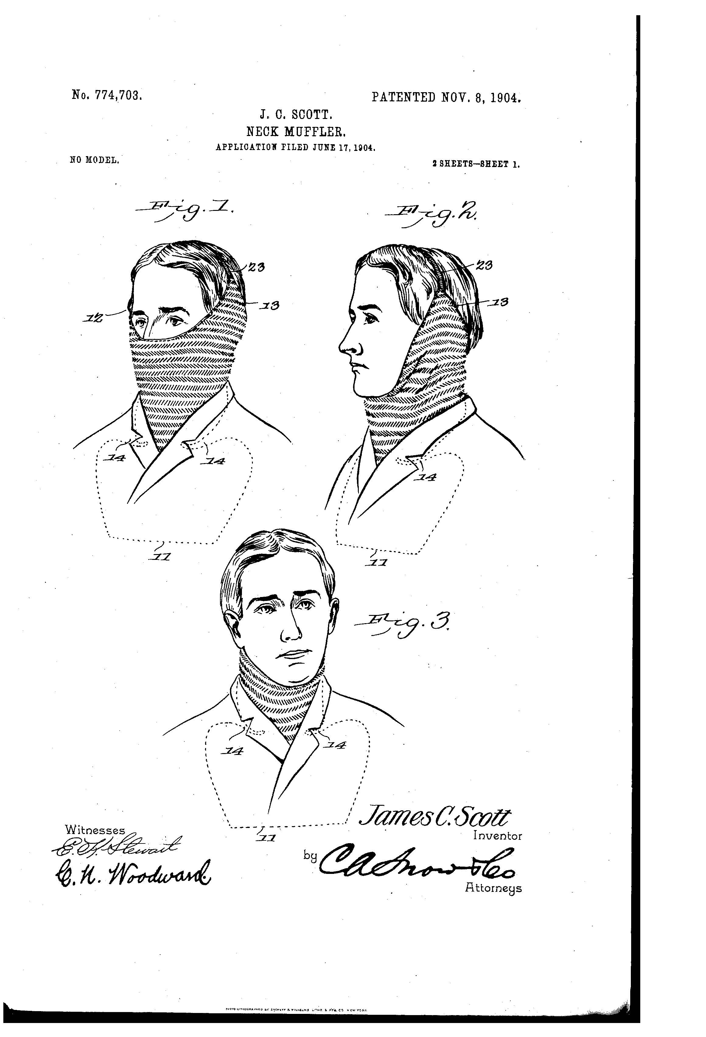
Patent of the Day: Neck Muffler
On this day in 1904, James Scott was granted the patent for NECK MUFFLER. U.S. Patent No. 774,703.
This invention relates to mufflers for protecting the neck, chest, or back or the ears and face, and has for its object to improve the construction and increase the efficiency and scope and produce a device of this character which may be quickly put on or taken off and adjusted to protect the neck and throat and chest or back only, or extended to protect the ears and face also, as required, and which will also adapt itself to the neck and shoulders and effectually prevent the entrance of cold drafts or moisture.

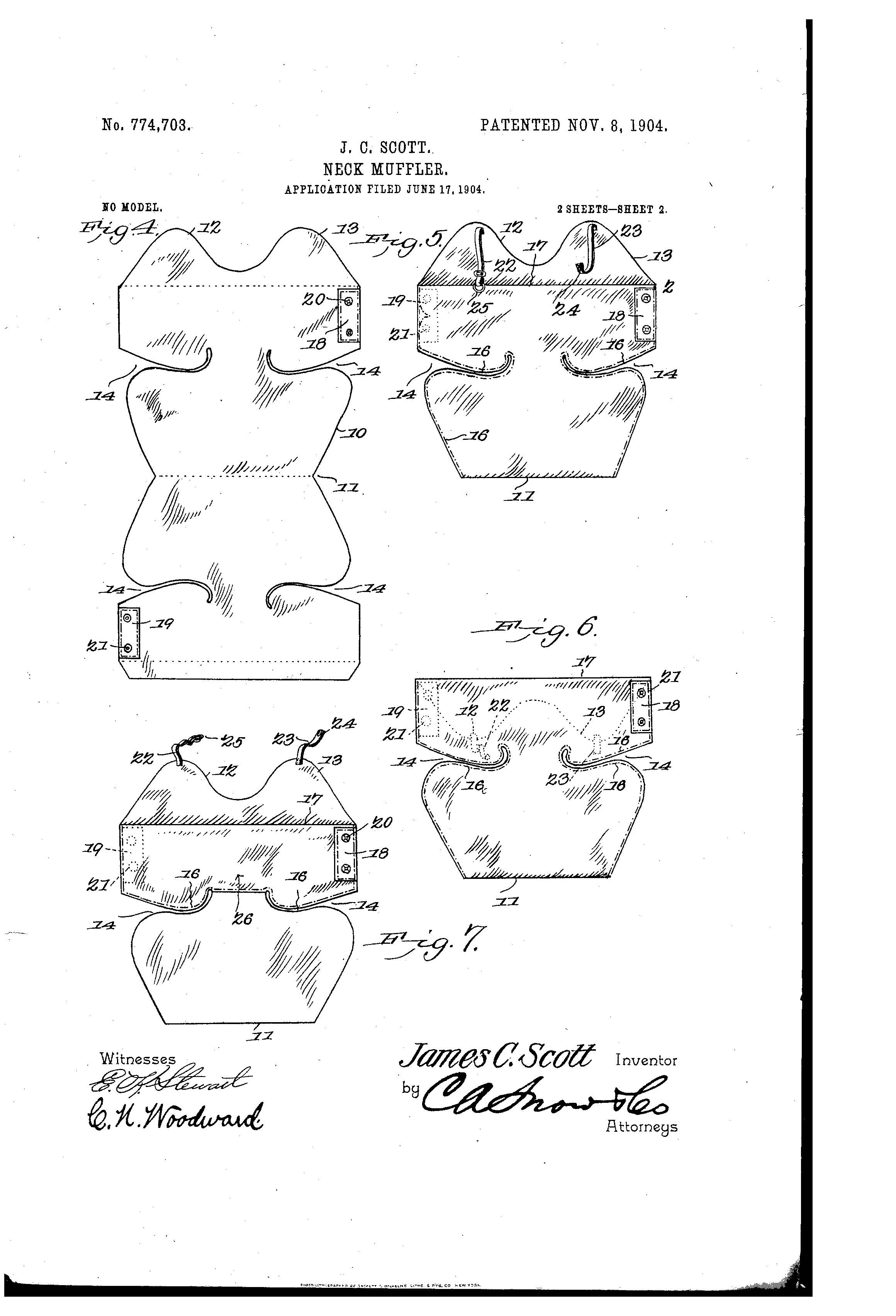
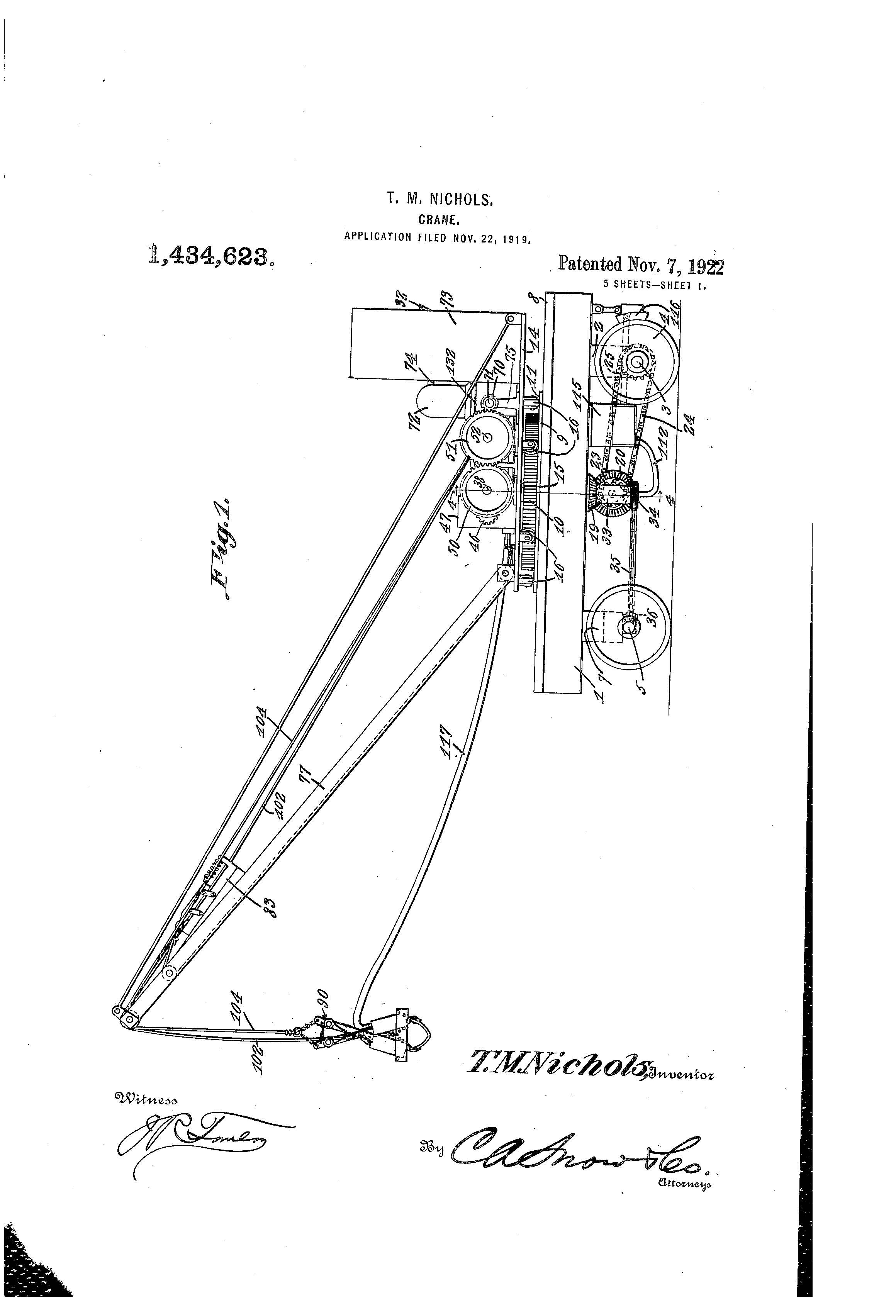
Patent of the Day: Crane
On this day in 1922 Thomas Millard Nichols was granted the patent for CRANE. U.S. Patent No. 1,434,623.
The device forming the subject matter of this application is a crane of that general type shown in prior Patent No. 1,307,412, granted on the 24th day of June 1919.
The present invention aims to provide novel means for propelling the truck, operating the turn table, and braking the movement of the truck.


Voting Methods, Machines and Intellectual Property

With the general election near, it is a good time to take a look at a brief history of voting machines and methods and the related intellectual property. The manner in which elections are conducted has changed over the years as have the various mechanisms used for voting.
 Voice Votes and Poll Books. In the United States, voice votes and poll books were used until the late 1800s. At the polling locations, voters were sworn in and then preceded to call out the names of the candidates of their choice to election clerks who recorded the votes in poll books. At that time, there was no secrecy involved with voting. On April 20, 1886, a patent was issued to William M. Kinnard of Dayton, Ohio for a combined tally sheet and poll book. (U.S. Patent No. 340,218).
Early Ballots. The first ballots in ancient times were not made of paper, but were small balls or tokens made of clay or metal. The word “ballot” is derived from the Italian word ballota; the Greek root means to cast or throw. Voters were given tokens or small balls to deposit (or cast) into a container for their candidate. The candidate with the most tokens was elected. More recently, societies like the Masons used black and white balls when voting on new members. A white ball represented acceptance into the society and a black ball represented a rejection. Hence the term “blackballed”. Many early voting machines used small balls, which enabled a voter to deposit a ball into the container representing the voter’s candidate of choice. The machine prevented a voter from casting more than the allowed number of votes in each race, and maintained separate ballot containers for each candidate. This method was used into the late 1800s—even after more advanced methods of voting were invented and in use.
Paper Ballots. Paper ballots were in use by the time the 12th Amendment was ratified (1804), evidenced by the following excerpt from the 12 Amendment: “they shall name in their ballots the person voted for as President, and in distinct ballots, the person voted for as Vice-President, ...” Early on, voters wrote the name of the candidate on a slip of paper and deposited it in a ballot box. Candidates and political parties eventually began providing preprinted partisan ballots. In 1838, the London Working Men's Association (Chartists) pushed for election reforms and secret ballots in England. The Chartists had influence in Australia and, in 1856, Victoria, Australia was the first to use uniform official ballots. The ballot was printed by the government and counted by hand; it became known as the Australian Secret Ballot. In 1888, New York and Massachusetts were the first states to use the Australian ballot and it was widely used in most states by 1940.
 Lever Voting Machines. Jacob H. Myers of Rochester, New York was granted a patent for the first mechanical lever VOTING MACHINE (U.S. Patent No. 415,549). This technology, eventually called Myers Automatic Booth, machine-counted votes. In 1892, the Myers Automatic Booth Lever Machine was first used in Lockport, New York. Lever machines were on the cutting edge of technology for the day and improved versions of these machines were slowly adopted through-out the country. By 1930, lever machines had been installed in virtually every major city in the United States.
Samuel R. Shoup and Ransom F. Shoup made a number of improvements to lever voting machines between 1929 and 1975. One improvement included a substantial, collapsible voting booth, that was relatively easy to transport and store. They were granted the patent for VOTING MACHINE on September 13, 1936 (U.S. Patent No. 2,054,102). Lever voting machines are no longer in production but are still used today.
Punch Cards. The standard punch card was patented by Herman Hollerith on January 8, 1889 (U.S. Patent No. 395,782), and was originally used to compile data  for the Baltimore Board of Health and the 1890 U.S. Census. This technology was not used in elections, but paved the way for future punch card technology. A punch card voting system utilized a pre-printed card attached to a sturdy board. Voters indicated their choice of candidates by punching through the appropriate hole using a stylus or a pen-shaped tool. The removal of a rectangle-shaped chad leaves a hole that is counted as a vote. The completed ballot is either dropped into a ballot box or fed into a computerized vote-tabulating machine.
Two types of punch cards systems have been in use, the Votomatic and the DataVote. The Votomatic cards have numbers that correspond to each hole. The list of candidates or ballot issues are printed separately and located inside the voting booth for reference. The DataVote ballot has the names of the candidates or ballot issues printed directly next to the punch hole. Joseph P. Harris, was granted a patent pertaining to Votomatic on August, 17, 1965 (DATA REGISTERING DEVICE, U.S. Patent No. 3,201,038).
Mark-Sense (Optical Scanner). Mark-Sense voting systems utilize pre-printed ballots with the candidates’ names or the ballot issues with an empty box, circle, rectangle, or arrow next to them. Voters indicate their vote by filling in the appropriate box, circle, or the like, using a black marker. The ballots are fed through a computerized vote-tabulating machine. The computer recognizes the darkest marks as votes and records them. James O. Narey and William Saylor were granted a patent in 1977, for a precinct-based optical scan system (U.S. Patent No. 4,021,780). This is considered the first model of the modern precinct-based optical scan systems that are in use today.
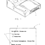 Ballot scanner systems developed by Election Systems and Software (ES&S) are examples of typical of central-count optical mark sense systems. Models differ in speed to accommodate various situations. Models with slower speeds suit small counties and are needed for processing absentee ballots that have been folded for mailing. Models with faster speeds suit counties with larger populations. An example of an ES&S patent for scanning is METHOD OF ANALYZING MARKS MADE ON A RESPONSE SHEET (U.S Patent no. 6,854,644).
Direct Recording Electronic (DRE) Voting Machines. McKay, Ziebold, and Kirby et al. developed a concept for an electronic voting machine, known as Video Voter for which they were granted a patent on February 19, 1974 (U.S. Patent No. 3,793,505). This patent was developed further by McKay, Smith & Deutsch for a commercial design of the Video Voter system. A patent was granted for this on May 24, 1977, (U.S. Patent No. 4,025,757), and may have been the first direct-recording electronic voting system to be used in government elections. DRE voting machines were the most 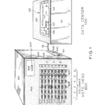 technologically advanced voting systems to be developed during the 20th century. The most commonly used DRE voting machines are the Electrovote 2000 and the Microvote. Since they are computerized, a hard copy ballot is not needed. The Electrovote 2000 is basically a pc and votes are cast by using a touch screen or push button. A keyboard is attached for write in votes. The votes are stored on a memory chip, diskette, or smart card. The Microvote is one of the older versions of DRE voting machines. The machine uses push-buttons to register a vote from a pre-printed ballot that is protected behind a window between the rows of buttons. The voter pushes the appropriate button to vote; a light indicates that a choice has been recorded.
From clay tokens to touch-screen polling systems, voting methods have come a long way. With today’s ever-changing technology and innovation, expect to see changes in voting methods and mechanisms on the horizon.
Office Hours December 1 at The Startup Collaborative
Suiter Swantz IP will be holding office hours December 1st at The Startup Collaborative, located in the Exchange Building in downtown Omaha.
Chad Swantz will be there from 3:00 - 5:00 pm. Feel free to send Chad an email (cws@suiter.com) if you’d like to reserve a time slot or have any questions. In addition, meeting times can always be made on an as-needed basis.
Suiter Swantz IP
402-496-0300
www.suiter.com
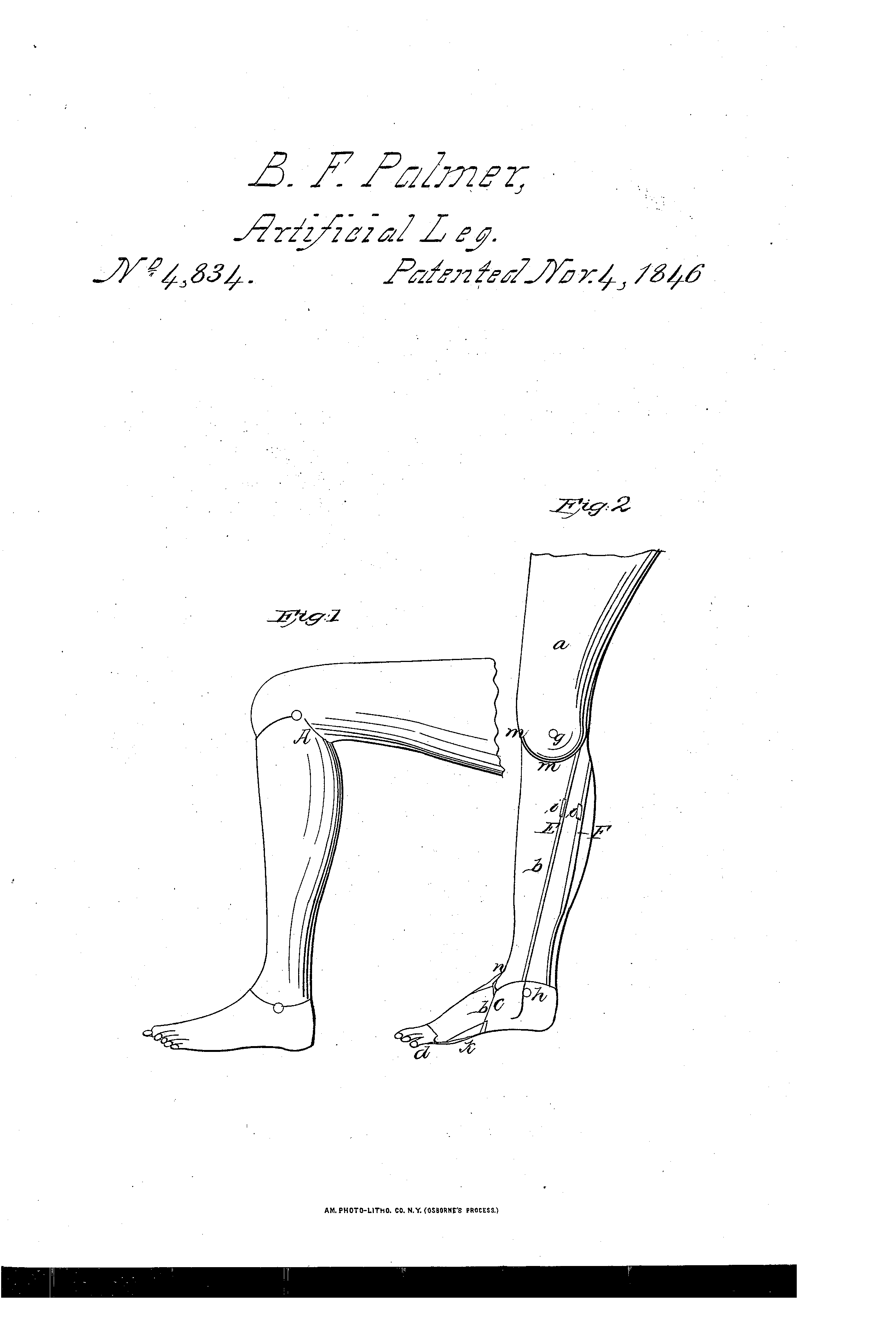
Patent of the Day: Artificial Leg
On this day in 1846, Benjamin Franklin Palmer was granted the patent for ARTIFICIAL LEG. U.S. Patent No. 4,834.
The nature of this invention consists in new and improved articulations of the knee, ankles, and toes, in constructing the various parts in such new manner as to leave no opening in the exterior of the leg about the joints, and supporting and arranging tendons and springs in such a manner as to give more elasticity, strength, durability and freedom of motion to the limb than are to be found in artificial legs.

New Memorandum Issued by USPTO on Software Eligibility

On November 2, 2016, the United States Patent and Trademark Office’s (USPTO) Deputy Commissioner, Robert W. Bahr, issued a memorandum in regard to “Recent Subject Matter Eligibility Decisions” from the U.S. Court of Appeals for the Federal Circuit (CAFC). Although the decisions do not change the basic subject matter eligibility framework, they will provide additional information regarding eligibility for software claims.
The decisions come from two recent court cases, McRO, Inc. dba Planet Blue v. Bandai Namco Games America Inc., 120 USPQ2d 1091 (Fed. Cir. 2016) and BASCOM Global Internet Services v. AT&T Mobility LLC, 827 F .3d 1341 (Fed. Cir. 2016).
In McRO, the CAFC held the “claimed methods of automatic lip synchronization and facial expression animation using computer-implemented rules patent eligible under 35 U.S.C. § 101, because they were not directed to an abstract idea.” (emphasis in original)
With respect to McRO, Bahr instructed examiners to “consider the claim as a whole under Step 2A of the USPTO's SME guidance” and they “should not overgeneralize the claim or simplify it into its ‘gist’ or core principles, when identifying a concept as a judicial exception.” Bahr also stated “An ‘improvement in computer-related technology’ is not limited to improvements in the operation of a computer or a computer network per se, but may also be claimed as a set of ‘rules’ (basically mathematical relationships) that improve computer-related technology by allowing computer performance of a function not previously performable by a computer.”
“An indication that a claim is directed to an improvement in computer-related technology may include—
(1) a teaching in the specification about how the claimed invention improves a computer or other technology…
(2) a particular solution to a problem or a particular way to achieve a desired outcome defined by the claimed invention, as opposed to merely claiming the idea of a solution or outcome…
In BASCOM, the CAFC “vacated a judgement of ineligibility because the district court failed to properly perform the second step of the Mayo/Alice framework (Step 2B of the USPTO's SME guidance) when analyzing a claimed system for filtering content retrieved from an Internet computer network.”
With respect to BASCOM, Bahr stated “In Step 2B of the USPTO’s SME guidance, examiners should consider the additional elements in combination, as well as individually, when determining whether a claim as a whole amounts to significantly more, as this may be found in the nonconventional and non-generic arrangement of known, conventional elements...” (emphasis in original).
Bahr also mentioned preemption, which has been discussed in several recent decisions. Bahr stated that this issue will be addressed in a forthcoming update to the subject matter eligibility (SME) guidance, but instructed examiners to “continue to use the Mayo/Alice framework… to resolve questions of preemption. If applicant argues that a claim does not preempt all applications of the exception, an examiner should reconsider in Step 2A of the eligibility analysis whether the claim is directed to an improvement in computer-related technology or a specific way of achieving a desired outcome or end result. [Also] [i]f an examiner still determines that the claim is directed to a judicial exception, the examiner should then reconsider in Step 2B of the eligibility analysis whether the additional elements in combination (as well as individually) are more than the non-conventional and non-generic arrangement of known, conventional elements.” (emphasis in original).
In closing, Bahr addressed the large number of precedential decisions and instructed examiners “to avoid relying upon or citing non-precedential decisions… unless the facts of the application under examination uniquely match the facts at issue in the non-precedential decision.”
Click on the link below to read the full memorandum.
https://www.uspto.gov/sites/default/files/documents/McRo-Bascom-Memo.pdf
Patent of the Day: Method of and Apparatus for Electrical Conversion and Distribution
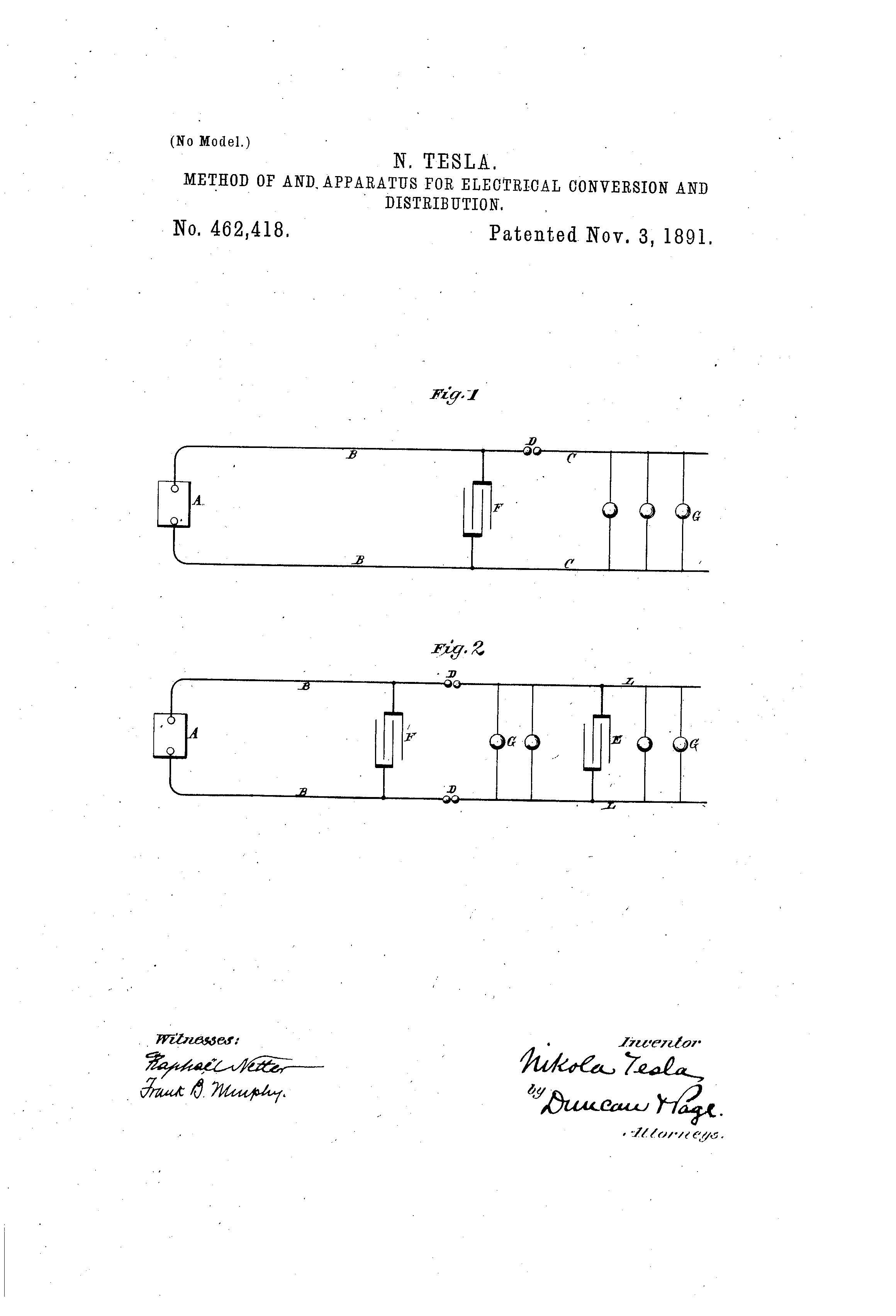
On this day in 1891 Nikola Tesla was granted the patent for METHOD OF AND APPARATUS FOR ELECTRICAL CONVERSION AND DISTRIBUTION. U.S. Patent No. 462,418.
This invention is based on certain electrical phenomena which have been observed by eminent scientists and recognized as due to laws which have been in a measure demonstrated, but which, so far as I am aware, have not hitherto been utilized on applied with any practically useful results. Stated briefly, these phenomena are as follows: First, if a condenser or conductor possessing capacity be charged from a suitable, generator and discharged through a, circuit, the discharge under certain conditions will be of an intermittent or oscillatory character; second, if two points in an electric circuit through which a current rapidly rising and falling in strength is made to flow be connected with the plates or armatures of a condenser, a variation in the current’s strength in the entire circuit or in a portion of the same only may be produced; third, the amount or character of such variation in the current’s strength is dependent upon the condenser capacity, the self-induction and resistance of the circuit or its sections, and the period or time rate of change of the current. It may be observed, however, that these several factors—the capacity, the self-induction, resistance, and period—are all related in a manner well understood by electricians; but to render such conversion as may be effected by condensers practically available and useful it is desirable, chiefly on account of the increased output and efficiency and reduced cost of the apparatus, to produce current-impulses succeeding each other with very great rapidity, or, in other words, to render the duration of each impulse, alternation, or oscillation of the current extremely small. To the many difficulties in the way of effecting this mechanically, as by means of rotating switches or interrupters, is perhaps due the failure to realize practically, at least to any marked degree, the advantages of which such a system is capable. To obviate these difficulties, this present invention has taken advantage of the fact above referred to, and which has been long recognized, that if a condenser or a conductor possessing capacity be charged from a suitable source and be discharged through a circuit the discharge under certain conditions, dependent on the capacity of the condenser or conductor, the self induction and resistance of the discharging circuit, and the rate of supply and decay of the electrical energy, may be effected intermittently or in the form of oscillations of extremely small period.


